
![]()
![]()

![]()
|
|
|
|
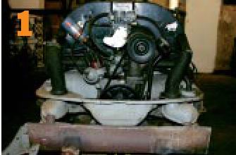
(From 6 Volts to 12 Volts) While 6Volts electrics are fine for those summer months cruising to and from shows, driving a six-volter at night can be a little unnerving. The reason for this is simple – 6V just doesn’t produce the juice necessary to light the way forward in a squint-free manner. 12V is where it’s at.
The array of modern Halogen bulbs available is mind-blowing. Once you have changed to 12V and experienced your new headlamps at night, you won’t believe you are driving the same car. This feature is the same for all upright-fan model VWs, so why not have a go at the conversion?
It is easier to do the conversion with the engine out of the car, though it could be done in situ. The time taken it takes to remove the engine is minimal.
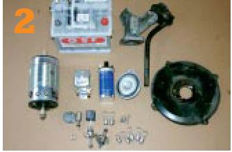
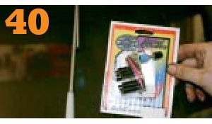
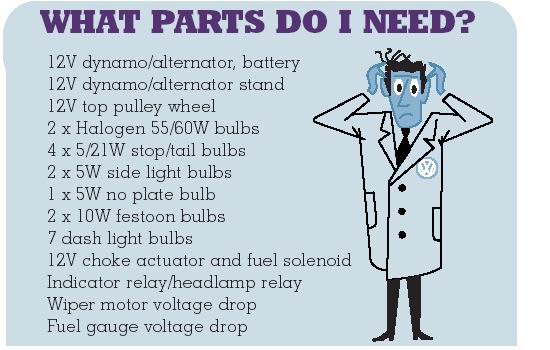
Here’s the collection of parts necessary to do the conversion.
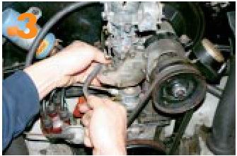
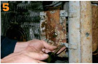
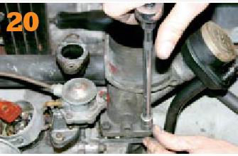
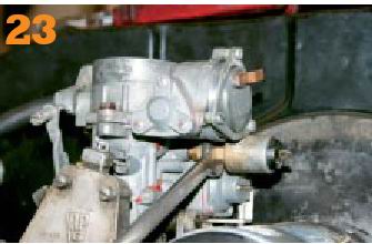
First task is to remove the carburettor. The rear nut is tricky blighter to remove, but a cranked 13mm spanner helps, no end and saves knuckles.
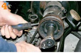
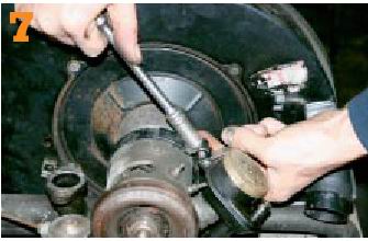
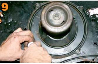
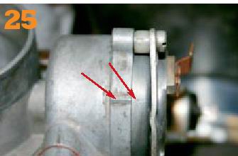
To slacken t6he top pulley wheel, insert a suitable flat-bladed screwdriver through the notches and use the screwdriver as a counter-lever. Undo the pulley nut anti-clockwise as normal. It may be tight, so many require force
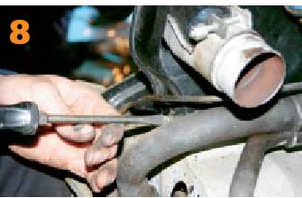
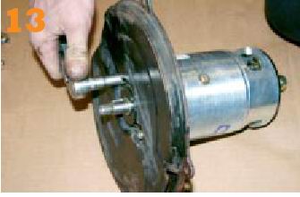
It will be necessary to disconnect the fan-flaps thermostat, which is located on the underside of the engine. With the help of a friend, flip the engine on to its flywheel end (avoid damaging clutch) and remove the lower tinware……
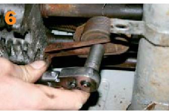
….to expose this little gizmo. Remove the support bracket first, and then unscrew the thermostat anti-clockwise. Check the thermostat still functions correctly by inserting it in a cup of boiling water to see if it expands properly.
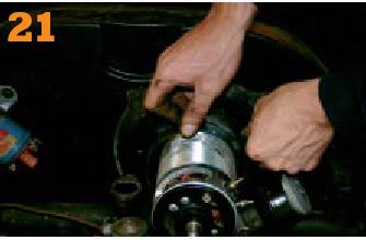
The main strap that holds the generator to the generator stand needs to be disconnected, at this stage. A 13mm socket and a spanner does the job nicely. Don’t forget to disconnect the wires going to the generator, too.
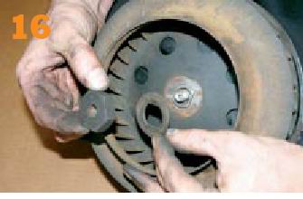
Undo the two slot-headed 6mm screws that clamp the fanhousing to the cylinder head tin ware. They are often seized so may require a good soaking in WD40 or equivalent. Try not to round off the heads of the screws if seized.
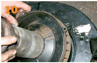
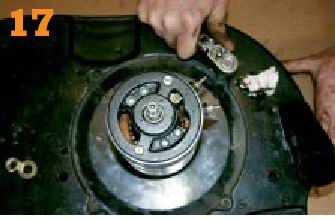
With the fanhousing removed from the engine and transferred to a bench, it is a simple task to remove the generator unit from the housing. Simply undo the four 10mm headed screws and the unit should…
….pop out with ease. As the unit is relatively heavy avoid dropping it on to a hard surface as the fan is easily damaged – it is only light gauge sheet metal. Check inside the fan housing for debris and leaves, and then remove.
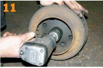
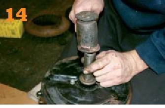
If you don’t have another fan at hand, it will be necessary to remove the old fan from the generator unit. By far the easiest way to do this is with an air wrench. Alternatively, use a breaker bar and 36mm socket.
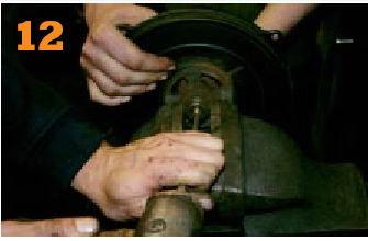
It will be necessary to remove the collet that supports the fan to the generator shaft. Clamp the collet in a vice; get an extra pair of hands to support the generator and using a hammer and drift drive off the collet.
As the collet is on a woodruff keyway it will require several sharp blows to remove. Undo the fan backing plate and transfer to the new 12V dynamo as above. Note that the backing plate has an exhaust port that faces down.
Once the backing plate is in place, drive on the fan collet. Use a deep impact socket and mallet to drive it on. It would be wise to support the generator in a vice to avoid any damage. Make sure the collet is driven fully ‘home’
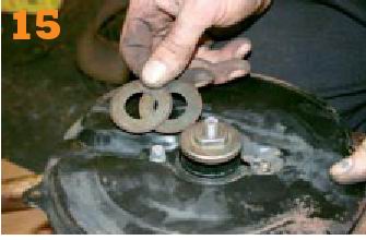
Don’t forget to shim the fan away from the backing plate. Start with the original shims and trial tha fan. There should be approximately 1-2mm of clearance between the fan and the backing plate. Add extra shims if necessary.
When you are happy there is sufficient, but not excessive, clearance between the fan and the backing plate, fit the sprung washer and 36mm nut and torque to specification. Avoid overtightening with a ‘windy gun’ (air impact wrench)
Offer up the generator unit to the fan housing and refit the bolts and tighten. It is a good idea to spin the generator by hand and listen for any signs of the fan rubbing against the fan housing. If there is any contact, re-shim the fan.
It will be necessary to remove the original generator stand because the new 12V items has a larger diameter and therefore, will not fit. Be very careful not to drop any foredign item down into the crankcase, for obvious reasons.
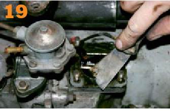
Resist the temptation to just slap on the new generator stand or a large oil leak will result. Clean off the old gasket with a suitable scraper and then clean off any gunk with solvent-based product and a suitable cloth.
Using two new gaskets and a thin smear of gasket sealant on both sides of the gaskets, slip on your 12V generator stand and refit and tighten the 13mm headed nuts to equal torque (approximately 15ft/lb)
Refit the fan housing and generator assembly to the engine. Don’t forget to re-fit the slot-headed screws at the end of the fan housing. Remember to re-connect the thermostat and lower tin ware. Fit the new 12Vgenerator strap.
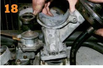
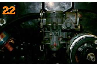
On the split-screen Bus we wanted to remove the speed governor, but with it removed, the carb fouled the generator. A switch to a later-style inlet manifold would have overcome this problem, but we didn’t have one to hand.
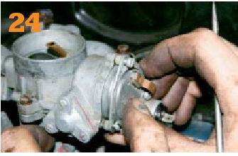
You will need to remove the fuel cut-off solenoid and replace it with a 12V item. Make sure you replace the sealing washer with a new one to avoid leaks.
The 6V choke bi-metal actuator will need to be replaced, too. Find one from an old 12V-style carb. Remove the three slot-headed screws and the unit should pull out easily. It is quite fiddly, so try not to lose the small pieces.
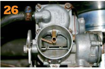
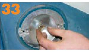
One often and easily overlooked point when refitting the choke actuator, is to line up the line cast on the carb with the dot on the choke actuator housing. Start with the two lined up as shown in this shot and nip up the screws.
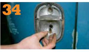
The correct position for the choke flap when fully cold is shown above. You may need to adjust the position of the flap by loosening off the three screws and rotating the actuator either clockwise or anti-clockwise, respectively.
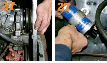
It will be necessary to use a 12V-style top pulley; otherwise the pulleys won’t be parallel as illustrated. Don’t forget to replace the original 6V coil with a new 12V one, otherwise the engine won’t fire!
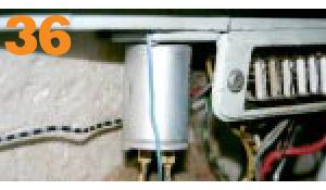
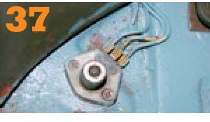
If you have opted for a dynamo over an alternator you will need to replace the voltage regulator.
It is quite likely that you will have to add new terminals, as shown above. Crimp-on are easiest.
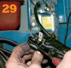
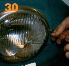
Now to the easy bits! Remove your headlamps by simply undoing the slot-headed screws…
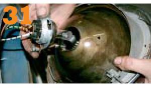
…. You will then be able to disconnect the bulb holder by turning it anti-clockwise. The bulb is simple to replace, but be careful not to touch the glass part of a Halogen bulb as it is to be avoided.
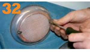
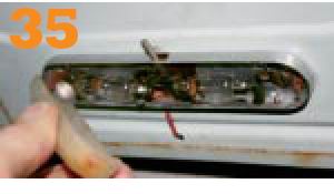
Indicators are simple to remove on both Bugs and Buses. Simply unscrew the securing screws and then the lens will pop off…
……. Revealing the original bulb. Replace this with a new 12V jobbie. You don’t have to worry about touching non-Halogen bulbs, as they can be touched without the glass being affected.
Tail light bulbs are accessed by removing the rear light lens on late Splits and all Bugs. On very early Split vans, such as 1957, access to the bulbs is via the rear of the light unit inside the engine bay.
One area often over looked until you switch on the light on for the first time since the conversion, and remark how bright your light now is (approximately two seconds before it blows). Is the interior light.
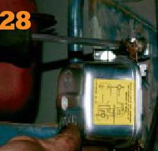
You will need to replace the original indicator/dip switch relay with a 12V one. If your vehicle is early enough to have semaphores, replace the bulb for a 12V item or run a voltage drop in-line.
Early Bugs and Splits run a floor-mounted dipswitch. This can handle 12V with0out problems…
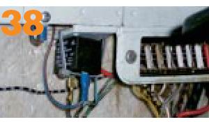
On a Split Bus the relay can be mounted to the original spot next to the fuse box with a little ingenuity and one of those superb little bits of plastic that help you out of no end of problems…
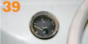
Opinions vary on the use of the 6V fuel gauge on Split Buses. Many people claim that theirs run fine with 12V pumped through them. Others swear by the use of a voltage drop…
6V wiper motors do run with 12V zapping through them, but they run at a warp-factor known only to Mr Scott and Captain K. Better to run a voltage drop.
|
|
Send mail to
eagleeye@searchmalta.com with
questions or comments about this web site.
|