![]()
![]()

![]()
|
|
|
|
Horn Wiring Hell (How to survive and understand it)
Symptom: Your horn doesn't work, you have a big fat
white button screwed to the underside of the dash of the Beetle you just bought,
your horn beeps itself whenever it wants to, all of the above. Introduction One of the real attractions to the VW Beetle is clearly its simplicity. Common sense, what is absolutely needed is there, what isn’t (ok, and maybe some that are), isn’t. But there are a few areas where things may seem a little needlessly complicated, and the horn wiring is one of those areas. An area that has been the source of untold frustration, embarrassment (that is when a horn announces itself with great fanfare, and long duration without any actions by the driver) and probably some of the most creative re-engineering I have ever seen. At least one of the several Beetles I have owned had a big fat white button screwed to the underside of the dashboard because some “mechanic” couldn’t figure the horn wiring out. But the wiring isn’t all that complicated, it just requires
a little explaining to understand (and lo and behold, that is what the BugShop
does best!). Lets start with the basics of how you would expect the horn to be
wired, then we'll get really deep into it and you'll see why VW did it
this way (maybe you will stop cussing them out) and lastly we'll talk
troubleshooting. Why does it have to be this way?
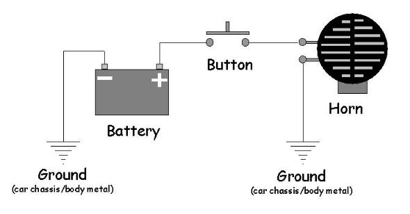
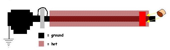
We all know
how simple electric circuits should be wired, right? This diagram shows the
typical “hot side switching” wiring that most people waltz into the world of
horn wiring expecting. Battery grounded, hot wire to push button, push button
to horn, then ground horn. It would be nice if it could be that simple, but it
is not. It is not that simple because that horn button has to be attached to
the steering wheel that must be able to rotate freely through several full
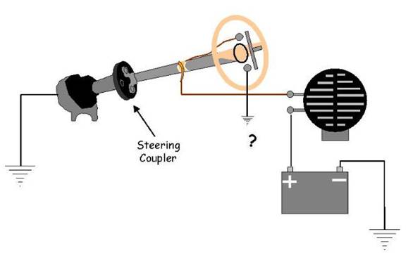
revolutions. If we just
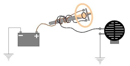
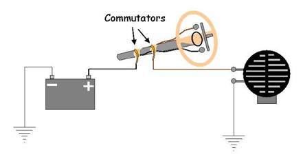
stick the button on the wheel, the wires get all wound up. What is needed is something called a “commutator”. Two of them actually. It's a device that allows electrical current to pass across one conductor that is stationary, to one that is rotating. A “brush”, just like the brushes in a motor or generator. Now since we are switching the hot side of the horn, we’d need two commutators; one to go from the stationary part to the button, and one from the rotating button back to the stationary part (note that in this drawing, the brushes and rotating bands are electrically isolated from the metal steering shaft). Well this might look like the best solution, and it certainly would work, but the thrifty VW engineers had to figure out the simplest and most cost effective way to accomplish that. Extra parts and especially extra stuff to wear out and break had to be avoided at all costs.
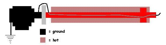
As it turns out, a “commutator” was already in place on the car before the engineers started messing around with the horn wiring. Know what it is? It's the steering box. You can pass current from the rotating steering shaft to the fixed housing of the box via the gears (and of course from there through the chassis all the way back to the negative post of the battery). Well that is all well and good, but since the box is grounded, it can’t do much good switching the “hot” side of the circuit. So the answer was to switch the negative side of the circuit. This is where some of the headaches come in (kind of like the late oval SWF turn signal flasher). Everyone with basic electrical circuit skills just jumps to the conclusion that the horn is positive side switched, especially when they pop the button off and see that little wire coming up the tube and touching it to the steering wheel nut (an apparent ground?) makes the horn sound. Read on… Ok, so we just move the horn button to the negative side of the circuit, and use the steering box to effect a path to ground… Ok, now we’re getting somewhere. But to accomplish what is seen in the drawing above, the VW engineers had to isolate the commutator from the steel shaft, and in the '59 and earlier models they did just that (there is a heavy cardboard under the copper band on the shaft).
Problem was, with the rubber-coupling disc at the steering
box, the shaft was actually isolated from ground.
But by simply adding a jumper over the steering coupler,
the steering shaft could be grounded. Hopefully now you understand why
it is done this way (so you can stop cussing at it). But this is the setup for
the '59 and earlier Beetles. Now let's see how this setup "evolved" over
the years following. Other Years... Of course not everybody drives a '59 and older Beetle, and as it turns out, VW dabbled with the setup many more times after that. And they are significantly different. So lets look at the other years and see how these changes were implemented. It gets a little complicated, but I think with the diagrams, you will be able to make sense of it. {And a BIG thanks to the guys at Wolfsburg West, who sorted out all of these year by year changes in a tech article in their monthly newsletter "Wolfsburg Wired" in December of 2000}
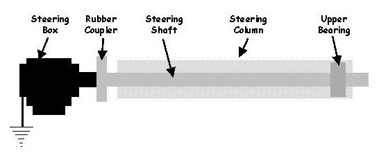
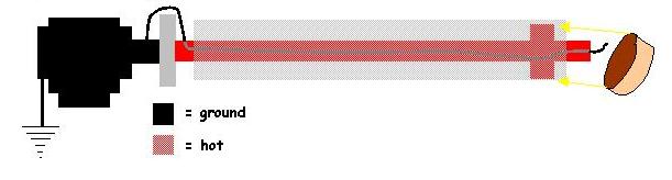
For the years after '59, we'll identify the "potential", or
voltage state, of several steering column points for each setup using the
diagram above. In '59 and earliers, a conductive upper bearing wasn't used. - '59 Switch "hot side" commutator is: Carbon brush/copper band
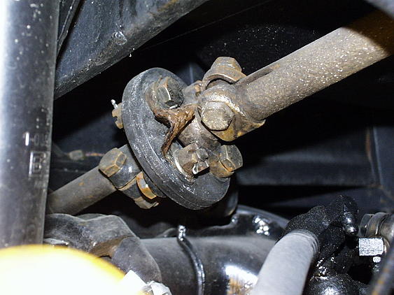
on steering shaft (isolated electrically from shaft) Of course I own a '57, so we can have pictures of that.
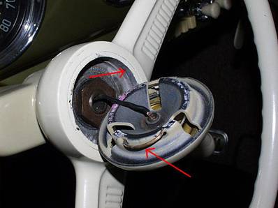
Here is the inside of the
button in my ’57. Now that wire runs down the hole in the shaft, then exits
about halfway down through a hole and connects to the copper band that is
isolated from the metal shaft by a cardboard band. The steering shaft in
this car is grounded, so the big fat nut and shaft end can be checked with
an ohmmeter for troubleshooting. Also, the button on these years is basically
self-contained, that is it has it's own spring and contacts. But it relies on
the connections to the steering column to work of course. One connection (the
"hot" side) is accomplished via that wire in the small screw terminal lug. The
ground connection is accomplished via the retaining clip/spring spring edges and
the steering wheel hub cavity sides, identified here with red arrows. Make sure
these areas are clean and shiny. This is a common problem with steering wheels
that have been painted and that area was not masked prior to paint application.
Here is the commutator on the steering column. Replacement
carbon brushes are available.
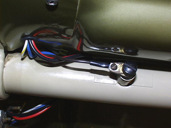
Here is the steering coupler. You can see the braided wire
strap that "jumpers out" the rubber disc. The two bolt up flanges on either
side of the disc are 90 degrees out of alignment with each other. So by
electrically connecting two adjacent bolts, you have effectively jumpered out
the rubber disc. '60 - '61 In 1960, the carbon brush commutator was discontinued. Instead, VW started using a steel ball bearing in place of the nylon bushing at the top of the steering shaft. Anyone who has a '60 or '61 Beetle and has had to scare up parts for the upper steering column knows just how hard these parts are to find. And almost everything about these years is unique when it comes to this two-year-only design. If you have one of these years with an original, working column, consider yourself very lucky, and take care of it. If you don't, and you will trade a working horn for vintage correctness, you might consider converting your whole column to the to the 1962-1967 type. '60 was the first year for the "dished" steering wheel by the way. This circuit functioned basically as combination of the earlier ('59 and back) and later ('62-'67) designs. It was like the '59 and earlier as it had a steering shaft that was grounded via a "jumper" over the rubber steering coupler. It was like the '62 and later in that it wired the column tube to the horn ground side and used the new conductive bearing as the second commutator (replacing the carbon brush used in the '59 and earlier). This wire attached to the bottom end of the tube, under the gas tank, just above the master cylinder. What was different for these two years was that while the upper bearing was conductive across its moving surfaces, its inner race was isolated from the steering shaft using a plastic shim/bushing. This meant that the column tube, the bearing itself were "hot", while the steering wheel was grounded as it was bolted to the shaft (grounded). Now you can get some idea of the complexity of the '60-'61 upper steering column. Using springs, washers and plastic shims, VW provided a current path from the turning inner race of the bearing, to the horn button area, without touching the metal steering wheel hub itself. It was very complicated, employed many plastic and metal bits, and springs and pins. No wonder it was dropped in '62... So the diagram for this type
of setup would be:
Switch "hot side" commutator is: Upper bearing (isolated
electrically from shaft) Now in '62, they figured out that the earlier design was needlessly complicated and that by allowing a conductive bearing (ie. one not isolated using plastic on either side of it) to be used between the tube and shaft the upper column design could be greatly simplified. "Ungrounding" the shaft was easy as it was connected to the grounded steering box via a rubber disk and the previously used copper braid strip could just be eliminated. So in this design, the whole column, bearing and shaft became energized as a unit, and a ground path was realized by running a wire down the hollow shaft, jumping over the rubber coupler and connecting it to the grounded steering box's input shaft. So in the '62 - '67 and later cars, if the steering column tube or the steering shaft (and wheel hub and nut) is grounded, the horn will sound. Now you know why that fat rubber grommet is needed where the tube passes through the firewall, and why you need that grommet at the upper end where the bracket holds it up under the dash.
Switch "hot side" commutator is: Upper bearing Of course this meant too, that the whole steering wheel
would be "hot" too, and like in the '60-'61 design, care must be taken to
electrically isolate the whole tube from the body using rubber grommets and
pads. '68 - '70 In this design, VW used a completely new steering column that bolted directly to the underside of the dash without rubber grommets/spacers. This might have been due to the fact that the ignition switch was now in the steering column (would you want to touch a "hot" key?). So VW went back to the plastic spacers again, this time on the outside of the bearing, to isolate it from the tube. So now the shaft and bearing was still "hot", but the tube was not. The ground wire came up the center of the shaft like before, but now the wire from the horn had to come directly to the bearing's outer race. Previously it was attached to the lower end of the column tube.
Switch "hot side" commutator is: Upper bearing (isolated
electrically from tube) '71 - '79 A brush and copper slip ring was added in to transfer current in the upper column (kind of sounds like that old '59 and earlier carbon brush doesn't it?). The bearing was no longer used as part of the circuit. A copper pick-up ring was mounted to the base of the steering wheel and a copper plate mounted to the turn signal switch applied tension against this slip ring allowing the current to pass through. From there, the brown wire was connected to the horn. Switch "hot side" commutator is: Copper slip ring between
steering wheel and turn signal switch Electrical particulars Now lets make sure we get the terms right. Ground is ground, chassis ground. Depending on the year of the Beetle, the negative side of the horn “floats” through the steering column in a variety of different ways. The horn button connects that floating horn negative side to ground via the wire that goes down the steering shaft to the steering box coupler. The horn positive (or “hot”) side is direct wired to the battery via a fuse. In 1962, when VW replaced all the screw terminal connections with spade lugs, the horn wiring moved from the unswitched fuse it shared with the wipers, to one it shared with the turn signals and that fuse was switched by the ignition. Thus, in the ’62 and laters, the horn would not sound unless the ignition was switched on. In 1960, VW figured that since the steering column tube was going to float hot with the horn anyway, why not just attach the horn negative side to the steering column? And since the lower/front end of the tube was near the horn anyway, it seemed like a good place to connect it. So the current path from the negative side of the horn was to the lower end of the steering column tube, up the tube to the steering wheel hub, and through the bearing/spring arrangement there (commutated) into the steering shaft/steering wheel hub. The wire connects to the tube base where it protrudes through the firewall, under the gas tank. Note also that, since the horn “floats” off ground and is switched on its ground side, you cannot use any aftermarket or other make of horn which grounds itself at the mount to the body. A horn with only one terminal will not work. And there is no “plus” or “minus” on a horn, it is a ungrounded, non polarized device, you can connect the wires either way. Lastly, the horn is a pretty high current device, especially the 6 volt ones (twice the current for the same power as a 12 volt one). This means that connections have to be clean and tight, and wires of the appropriate gauge. I would wire a 6 volt horn with 16 gauge wire minimum, 14 gauge wouldn’t be a bad idea. I haven’t actually measured the current, but my guess is that it would be in the 5+ amp range. So that little horn button is switching a pretty decent load, make sure that its contact points are clean and shiny. Emery cloth them. Also, that poor horn has to live up under the fender in a really nasty environment. Those terminals can corrode real fast. (Wolfsburg West sells the little boots for the early ones) Check them carefully. The carbon brush for the ’59 and earliers is also available from WW. Go to
www.vintagebus.com for an excellent
collection of wiring diagrams for a wide range of years. Troubleshooting Now that you know how it all works, troubleshooting should be easy. Right? First, verify that the horn itself has power on it’s “hot” side. Note that the horn does not ground electrically to the body at its mounting point, unlike exterior lights and just about every other electrical device on the car. So read voltage at the terminal that should be connected to hot. And BTW, you may read voltage on both terminals if the wires are connected (unless someone is blaring it while you are under there in which case it will be REAL annoying). This is because the horn will pass voltage through to the meter while it is off. Disconnect the wires from the horn and read the voltage at the wire ends to ground. If no voltage, trace wiring path all the way back to fuse box and then to battery. Next, verify continuity between the other wire (while not connected to the horn) and where it is going. You'll have to apply the year by year particulars listed above. If it is a '59 and earlier, you'll trace it back through the carbon brush and up to where the brown wire exits under the steering button. For '60-'61s, it should go to the base of the column tube and have an electrical connection up the tube to the hub. If it is a '62-'67, same thing, but you should have continuity to the steering shaft (and wheel hub and nut) as well. Use your meter “ohm” scale for this, you should see a 0-1 ohm reading. For the '68 and laters, you'll have to chase that wire up through the steering column hub (I think it goes in with the turn signal harness wires) and to the outer upper bearing race. Last, verify that the little wire that comes up through the middle of the steering shaft is tied to ground at the end for the '62 and laters. For the '61 and earliers, make sure the copper braid strip (or a simple wire substitute) is in place at the rubber coupler and has a good connection. For '61 and earliers, read ohms between the steering shaft (or its nut) and some metal on the body (one of the bolts that holds the upper steering column bracket is a good ground). If it is “open”, the wire/braid might have broken off (or been left off) the steering box side of the rubber disc coupler. Much more unlikely, but possible, is that the steering box is not making a good ground with the front beam. If you suspect the button, remove it, and just touch the wire coming out of the snout of the shaft to the steering wheel nut. For '62 and laters, a quick voltage check, is to read voltage between the steering wheel nut and and ground. If the horn is powered up (ignition on?) and everything on the “hot” side is OK, you will see voltage there (a small light bulb between them will light up!). If your horn sounds all by itself and embarrasses you, you probably have some short between the steering wheel hub, shaft, or tube and chassis ground. Sometimes this happens within the turn signal switch and the horn sounds when the wheel is turned just right. Herbie’s horn in the Disney movies did this…. ! Hopefully that clears it all up for you. I have never owned anything newer than a ’68, so I’m not too sure of the details in the later models, but I think it all worked basically the same. Now if you have an annoying horn problem, take your newfound knowledge and go out and fix it!! (WW- '59) Most of the problems with this circuit are Interesting Side Note: During the week I was writing this article, Travis Hall, a '63 Beetle owner, posted this message over at the aircooled newsgroup. He has a bare metal (chromed) chain-link steering wheel on his '63: "Hi all. I have a '63 bug that really shocked me the other
day. I mean "The horn is hooked up on this steering wheel and I suspect
(haven't pulled Travis
|
|
Send mail to
eagleeye@searchmalta.com with
questions or comments about this web site.
|