|

by Jeff Martin
Summary:
This is a short How to; on the
installation of the BugPack Linkpin front beam adjuster.
Comments:
This is a short How to;
on the installation of the BugPack Linkpin front beam adjuster. It should give
everyone a good idea on how to install these units. Since my beam is Linkpin I
will not cover the Ball Joint front end installation which is essentially the
same but has a few more steps. You should also carefully follow the instructions
that came with your adjusters. This article is meant to help visualize the
procedure; it does not replace the instructions that came with your adjusters.

Here is the front beam removed from the car. It's best to refer to a shop
manual if you have never done this before.
Scratch or mark a 3" long line, lengthwise along the top tube, through the
center of the set screw. If you have a balljoint front end, mark another 3" line
parallel to the first one and 1 5/16" above it. Next, mark the exact center of
the tube, vertically, throught he set screw hole and at right angles to the 3"
inch mark. Then mark your cutting line 1" to each side of the center line.
Here is the front beam with the center
2" removed.
NOTE: If you want to have all of your height adjustment in either the upward
or downward direction, it's possible to set the adjust for the effect before you
go on. If you want only downward adjustment you should set the adjusting block
and it's socket set screw as far back from the bracket as possible. Set it in
the middle to allow for equal amounts of upward and downward adjustment. Then
continue on.
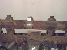
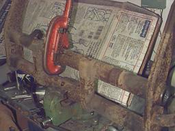
Once you set the adjuster for the selected adjustment. Place the whole unit
in the tube, with the disk turned down. The marked line should pass through the
center of the new socket set screw. The unit should be placed so that the sleeve
assembly and set screw point to the front of the car. The adjuster block and
it's set screw should be on top. Tack weld the adjuster in place and test it for
straightness by inserting your leaf springs. They should be centered at both
ends of the tube. Pictured here is the back of the beam.
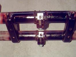
Here is the finished beam. I've only painted the adjuster part of the beam
because I found some rust on the lower shock tower sections that has to be fixed
before it can go back in the car. I am very happy with how the adjusters turned
out.
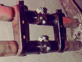 
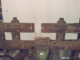
Another picture of the welded in
adjusters from the side. Note in the background you can see the rust on the
lower shock tower near the snubber mount.
The bottom adjuster is not crooked, merely the aluminum adjuster block is. I
verified this by putting in the leaf springs as mentioned in an earlier step.
Adjustment is made by loosening both jam nuts and the set screw with the
block on it. Turn the adjusting set screw to your desired position and retighten
the set screw and both jam nuts. If you have more than one adjuster in your
front end, make the adjustments all at the same time. Torque the set screw to 30
foot pounds and the jam nuts to 55 foot pounds. Note: your Bugpack adjuster,
when set in the middle, will give you 20 degrees of adjustment up or down, for a
total of 40 degrees of adjustment. In terms of gournd clearance, this is about
2" up or down, or a total of 4".
|