|

By Thomas Simpson, aka. "Ohio Tom"
Editor's note:
No matter what type of engine you are building, weather it is a mildly-tuned
1600cc daily driver, or a full-blown 2275cc street-n-strip monster, one of the
most important ingredients is the cylinder heads. Why does one person's 1914cc
engine outperform another's 2275cc engine? The answer often lies in the cylinder
heads. One of the most important rules of high performance building is to
remember that the horsepower is in the heads.
The total investment in the cylinder heads of a high performance engine can
represent a significant portion of the entire engine budget, and in the search
for horsepower, you can't go wrong ordering a set of heads from one of the
cylinder head gurus. But what if your budget is not within the "guru" price
range? Noticeable gains can still be made by the do-it-yourselfer through
careful portwork and attention to detail. Follow along as Thomas Simpson walks
you through the basics of head porting.
This is a description of basic porting techniques used to port a stock VW
casting, Type 1 heads. These include the 040, 043, and 044, with either stock or
40mm x 35.5mm valves. Heads with larger valves should have much more porting
work done in order to flow to their full potential. My sources are Bill Fisher's
How to Hotrod VW Engines (1970), various articles, and my own personal
experimentation. I am not a professional. Their trade is truly one of a Black
Art form. Don't expect your heads to flow as well as a professional's would.
I like use a rotary file of different shapes (ball, acorn, and tulip shape). For
finishing, I use a sanding roll and small flap wheels (80grit). These are all
available to fit a Dremel Moto tool, available at any well-equipped hobby or
hardware store. To keep things the identical, I like to do one step at a time to
all 4 ports before moving on to the next step. This process usually takes
approximately 10-20 hrs. to complete.
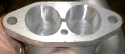
(Note: for the purposes of this article, the heads pictured are for a turbo
motor, and have the exhaust guide bosses removed. This is necessary for turbos
under high boost, however I do not recommend this for a normally aspirated
motor, as it will shorten valve guide life).
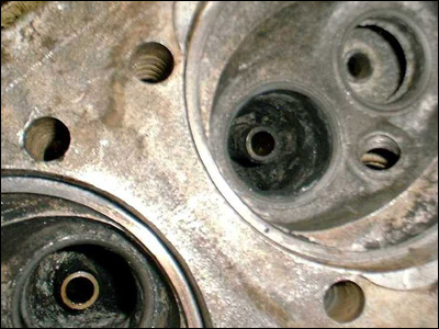
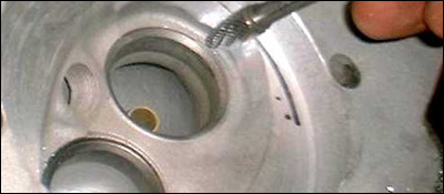
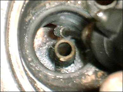
A diamond in the
rough. Refer back to this picture for comparisons. Note the sharp edge just
below the exhaust valve seat.
These steps apply to any
head of any type:
Valves and Seats
The use of stainless steel valves will always improve flow over standard stock
valves, as they have a much tighter radius on the backside, allowing for less
obstruction at the opening when the valves are open at low lifts. A good
3-4-5-angle valve job will enhance the flow improvement even more. You can pay a
professional to do this work. I have access to some really nice grinding stones
at work and have good success grinding the valve angles by hand, with the
exception of the sealing 45 degree angle. I leave that one alone.
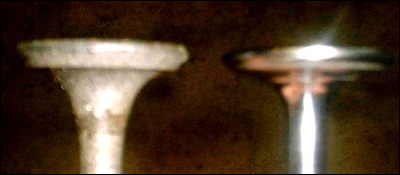
Note the tighter
radius on backside and removal of the sharp corner of the 45 angle. The head has
a radius all the way around.
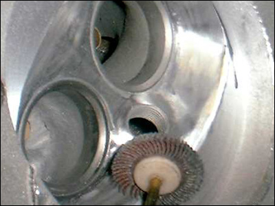
Port and Chamber Area Around the Seat
The valve seats are steel inserts pressed into the aluminum casting. There is
usually a mismatch of metal in the port and in the combustion chamber. Take time
to blend the port and chamber until the step (mismatch) is gone, using your
finger to feel for imperfections. When working around the valve seat, take
extreme care not to accidentally nick the 45 degree angle in the set, or you
will be taking the head to the machine shop for dressing the seat. If the heads
are used, the do the port work first.
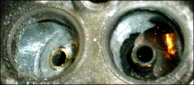
Blending the
seats into the port runner. Note the absence of the exhaust guide boss (for
turbo applications only!)
Combustion Chambers
Too much deck height is a bad thing, resulting in loss of turbulence
at TDC when the mixture is ignited and reduce combustion efficiency. Deep
combustion chambers are another problem, as they tend to shroud the valves
giving very little room for flow around the valve into the chamber. I like to
lay back both the plug side and non-plug side of the chamber by widening the
angles. I also unshroud the valves by opening the sides of the chamber up to the
cylinder bore diameter. I then blend all this together, smoothing all
imperfections and casting marks. This means that the chamber is opened up all
the way around, making for a much clearer entry for gasses into the cylinder
(and exit for the exhaust). I then flycut the heads to get the desired chamber
CC's (with .050" - .070" deck height). I then use a flapwheel to remove the
sharp edge all the way around. Take care not to round the sides where the
cylinder will seal against the head. It is a good idea to scribe a line around
the head where the cyl will meet the head, and to drop some junk valves into the
heads to protect the valve seats while working in the chambers.
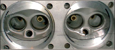
Use a cylinder to
scribe or draw a line around the inside of the bore, marking where you perimeter
to unshroud the valve. Compare this photo to the finished chamber photo later
on.
Unshrouding out
to the scribe line.
"Laying Back" the
plug side of chamber (reference lines are used to clearly demonstrate the
amount).
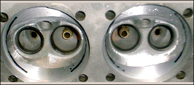
Non-plug side layback. Note that it is not as drastic as the plug side as there
is less flow to be gained on this side.
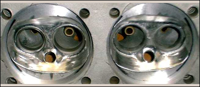
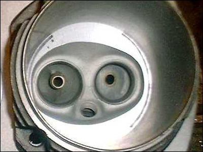
Finished chamber
after polishing with a flapwheel.
It is important to deburr
all sharp edges in the chamber. I knock off the corners with the flapwheel. This
also shows the new "layback" angle of the chambers. Intake Ports
The goal is to provide the
best port-match for a 35.5mm or 40mm intake valve. "Hogging it out" is not the
goal. The stock size port does not need to be enlarged very much to get good
results, and too big of a port will cause a loss of port velocity and create
unwanted turbulence. The goal is to reduce the restriction of the port.
Set the head in front of you with the intake flange facing you (right side up).
The ports are round, and we are going to make them oval in the direction of the
sparkplug holes, similar to a "V" shape. If you have a intake gasket or pattern
to borrow, now is the time to draw/scribe it out onto the intake flange. Hold
the grinder perpendicular to the flange and open up the ports to the new port
shape. Don't worry about blending into the port yet. Take your time and make all
the port openings look the same.
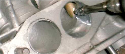
note
the scribe line on the left port. The right port is almost there. Also note the
angle of the rotary file is the same as the port entry angle, keeping things
matched to the intake manifold (later).
Set the acorn file out as
far as you can in the grinder to give maximum reach into the port. On most heads
the port has a casting part line right above the intake guide boss. This part
line makes for a major corner right above the guide boss blocking any flow
trying to go over top of the guide (Bill Fisher's book has some good pictures of
this area). You will want to blend this corner away by plunging the grinder down
through the port going over top of the guide boss. Once through, work from the
chamber side of the port to blend the contour. There is a fair amount of metal
to remove here so take your time and study the port closely. The goal is to make
the port above the guide look like it does below the guide, in effect
straightening the port. This will open up a new flow path for intake charge. I
also like to thin the intake guide boss, as it does very little anyway. Shape
the metal into a nice teardrop shape around the guide, working from both ends of
the port (the heads used for these pictures, however, have no guide bosses).
Stock
port.
The work done to straighten
the flow above the guide.
Blending into the port.
Once the major porting has
been performed, blend the whole port together, removing all the bumps and
corners, radiusing the port into the new openings. Use your finger to feel for
irregularities. The contour should be one nice smooth blend all the way to the
valve seat. Work slowly!
finished port after
blending the contours.
Exhaust Ports
I
pretty much go by the book here. Without removing too much guide boss material,
I like to contour the boss much in the same way that we did the intake bosses.
Because the boss takes up so much of the port in that area, it helps flow to
widen (or squeeze) the port around the boss. Working from the seat side of the
port, start widening the port on either side of the boss just below the seat.
You can blend these wide pockets into the port from the exit flange side. There
is a sharp edge on most heads on the inside radius of the port, and it is almost
impossible to see (you have to use your finger to find it). Tighten-up the
inside radius, leading away from the seat, blending this edge away. Do not take
too much material away here or there will not be enough left to support the seat
properly. Lastly, open up the port at the header flange. Use an appropriate size
exhaust gasket for this pattern. Note: a 1 5/8" header has a 1 ½" ID, so measure
the pipes. Now, as before, blend everything into a nice smooth port with no
bumps or sharp radii.
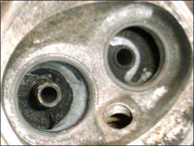
Compare this photo to the
lead one (photo #1). The radius of the port under the seat is not visible, but
it is there. You can see that the guide boss has been thinned and shaped.
Finishing Up
I like using a flapwheel
wherever I can, as they do a great job of smoothing out the bumps and blending
everything (and they last a long time). If the flapwheel will not smooth it out,
go back to the rotary file. If you have done it right, you will have a
professional looking port job. With any luck you will have one that flows almost
as good as a professional port job as well.
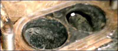
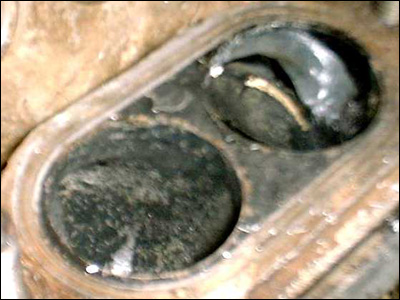
Match-Porting
To take full benefit of
your efforts it is important to match-port the intake manifolds. I use the same
pattern gasket and transfer the port shape to the manifold base.
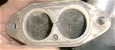
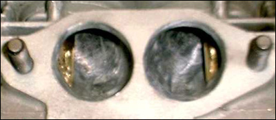
Photo's 16 and 17; before
and after. These manifolds match up perfectly to the heads. Note that these are
stock castings for use with a draw through turbo system. The same principles
would apply with any other manifold used.
What to Expect
I have done several
sets of heads exactly as described here. These stock-valved heads on a 1585cc
motor with a "hot" cam and dual 44IDF carbs ran 15.38 et ¼ mile times and made
power to 6,700 rpm in my 73' Super Beetle. You can run these heads on a stock
motor or 1775cc with good results. You can run a stock carb. or dual Weber carbs.
on them. Due to the level of polishing in the chambers and improved combustion,
you can safely run higher compression than a stock engine without the risk of
overheating and detonation.
Good luck and remember, this is free personal advice.
|