
![]()
![]()

![]()
|
|
|
|
O.K. so you’ve built your first hi-po engine and are wondering whether your stock fuel pump is up to the task of feeding over 150 thoroughbred horses… Fuel systems are often neglected when it comes to high performance engines. Maybe it’s sometime a lack of experience that lets down an otherwise sound performance upgrade. All too often we’ve seen great cars with superb engines let down by inadequate fuel supply, which at best reduces performance, and at worst can melt an engine down in seconds. When an engine runs lean on fuel it has a tendency to cut like a blowtorch and melt the pistons before you know it. You end up with a very expensive pile of junk for which you spent the last two years savings. The stock fuel system relies on a fuel tank supplying fuel via a 4mm bore fuel line on most air-cooled VWs. The fuel needs to be sucked up the length of the fuel line to the fuel pump by means of a mechanical fuel pump designed to flow adequate fuel for a 50 horsepower engine. Hang on a minute, your 2.3 litre, big valve, IDA crested strocker has just been dyno’d at a 160bhp. Believe it or not there are cars out there running stock fuel systems after having spent upwards of five grand on a performance motor. OK, so the motor runs, but there will always be a question mark hanging over its integrity. Fuel system upgrade need not cost the earth. Decent electric fuel pumps and fuel pressure regulators are available from most performance part suppliers. Fuel lines can be upgraded to larger bore hose for less than a night at the boozer. The only real investment will be a little ingenuity and time. After all, we love tinkering with our rides, don’t we? For the record, most engine builders rate the stock fuel system to approximately 100bhp, so if you are running more than that, you may well want to address your system ASAP.
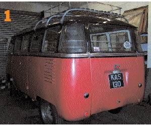
The subject in our feature is an awesome turbocharged 2038cc Barndoor Striker. Obviously, with over 200bhp on tap the stock fuel system wouldn’t be up to the task of keeping the fuel flowing.
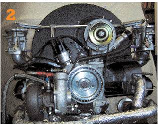
Here’s a shot of the engine prior to installation. The spec is 90.5x78.8mm, ported and polished 044’ heads with 42x37.5 valves. The turbo is a Schwitzer S2A – ideal for a heavy Bus. Carbs are turbo-spec Dellorto 40s
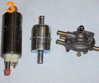
A shot of the major fuel system components. From left we have a roller vane fuel pump, hi-flo 12mm filter and the adjustable boost sensitive regulator.
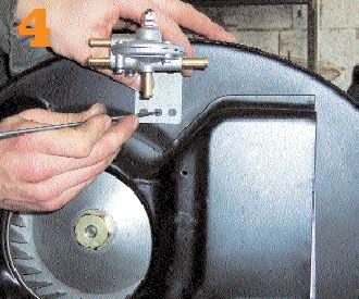
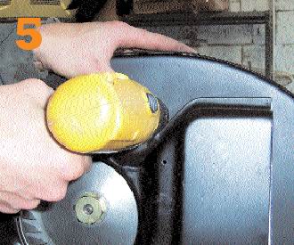
As the engine was out of the vehicle, it was simple and neat to mount the fuel pressure regulator to the back of the fan housing.
After scribing around the mounting bracket holes, the fastener holes were drilled and then some riv-nuts were riveted in place.
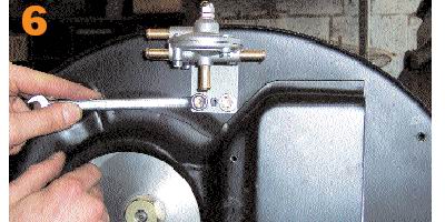
This allowed the pressure regulator to be mounted to the fan housing. On turbo pressure regulators there are usually two extra pipe connections; one is fed to boost pressure and the other returns excess fuel to the tank.
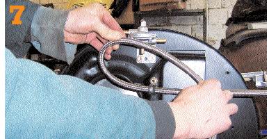
The next task was to work out the fuel pipe to carb lengths. Whenever bends are required, it is imperative that the bends form a gradual radius otherwise they can kink and reduce fuel flow to a trickle.
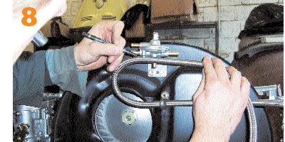
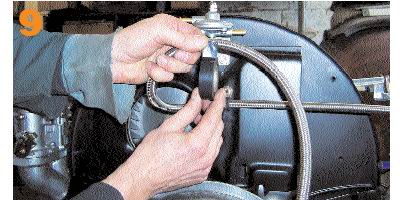
our installation required stainless braided hose for aesthetic as well as functional purposes. You don’t necessarily need this expensive option, but it sure looks the part. Here we are marking where the hoses needs to be cut.
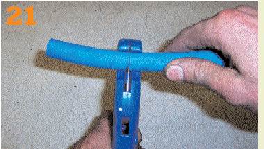
Stainless braided hose is an absolute pain to cut because each strand frays easily and pricks your fingers given the slightest opportunity. I find wrapping the hose with insulation tape prior to cutting the hose minimises fraying.
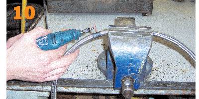
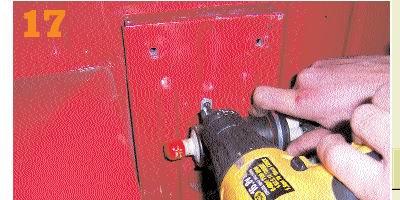
Now comes the tricky bit. There is no easy way to cut stainless braided hoses, but over the years I have found that cutting the outer braid with a Dremel and a fine cutting disc works best for me. Remember to wear eye protection.
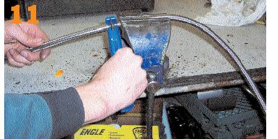
Once the outer braid is cut, it is then possible to cut the hose with pipe cutters. This makes a clean cut with no debris entering the hose, which would have been the case had I cut right through with the Dremel.
As this engine has twin carbs we chose a regulator with two fuel pressure outlets. A single outlet would have required the use of a T-piece, which greatly restricts fuel flow – not advisable on a turbo engine.
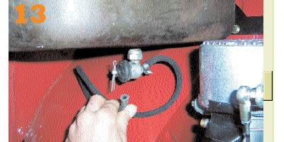
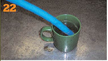
On to the stock fuel tank and out let. Here’s an illustration of how restrictive the tap and hose are. The internal measurements of the fuel tap are just 3.5mm – OK for 25 poniesa, but not up to the job of fuelling 200 stallions.
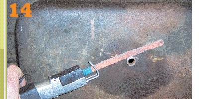
The next step was to remove the fuel tank from the vehicle. It is ABSOLUTELEY VITAL that you drain the fuel and wash it out with detergent to remove any trace of fuel. Any vapours will cause an explosion and therefore may be very painful.
Repeat- drain fuel tank and remove any trace of fuel with detergent before attempting and cutting, drilling or welding on the tank. Your life could be at risk. We opted for 8 JIC fittings for the fuel outlet.
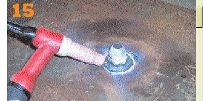
The next stage was to find a suitable location for the fuel pump. Electric pump installations normally require the pump to be situated lower than the fuel level in order for the fuel to gravity-feed the pump.
Here the pump mounts are being marked so that permanent fixings can be fitted to hold the pump in place.
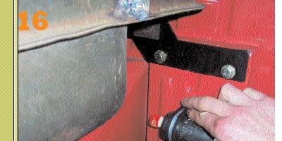
With the pump mounted and the fuel line connected, the pump was then wired to the loom. Fuel pumps draw a fair amount of current, so it is wise to feed a separate fused supply regulated by a relay.
If electric fuel pumps have a weakness, then it is dirty fuel. Bits of rust and other crap prevalent in fuel have a habit of wrecking the internals of rotary vane pumps. A hi-floe filter was placed BEFORE the pump to eliminate this.
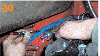
It is simple to make a clean installation if you take a little time to measure and mark the lengths of fuel line. Felt tip pens are superb at marking most things; especially blue fuel pipe.
Cutting fuel hose is made simple with a pair of plastic pipe cutters sourced from a plumber’s merchants. They are designed for cutting central heating pipes, but work fantastically in workshop mode.
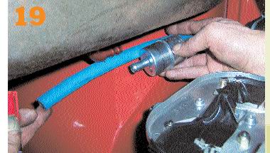
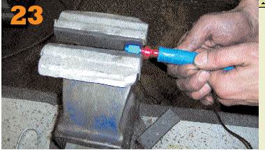
The goodridge Aeroquip hose used for the tank supply to the fuel pump is best soaked for a minute in boiling water prior to being……
……mated to its Aero quip fitting. As the fitting is anodised aluminium it is easily marked and damaged. This is easily prevented by using rubber on your vice jaws.
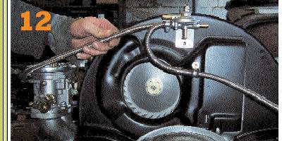
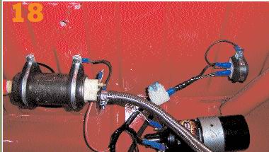
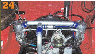
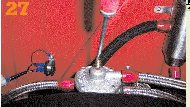
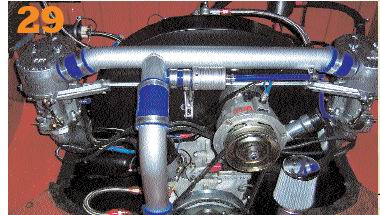
As you can see, blow-through turbo engines get a little busy with pipes going here, there and everywhere. Pipe from the top of the pressure regulator connects to the boost tube. Note the fuel return to top of tank.
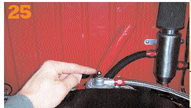
Initial fuel pressure is adjusted by means of this little screw. First undo the lock nut to reveal a screw and second lock nut.
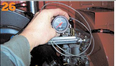
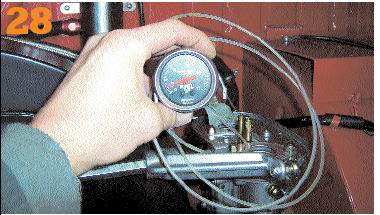
To set tha fuel pressure it was necessary to couple a fuel gauge into the fuel line to one or the other of the carbs. A good quality gauge is essential, as fuel pressure needs to be set accurately.
Winding this screw in or out sets fuel presuure. In increasing pressure and out reducing it.
Fuel pressure for Webers or Dellortos is best set to no morfe than 3psi. any more than that, and you run the risk of frorcing the floats to regulate the fuel bowls improperly. This may result in ‘flooding’ the engine with fuel.
Once the fuel pressure is set and the lock nut locked, that should be all you ever need to do to the regulator. The finished fuel system installation looks tidy and functions superbly. Unleash the power. Build yourself a fuel system. |
|
Send mail to
eagleeye@searchmalta.com with
questions or comments about this web site.
|